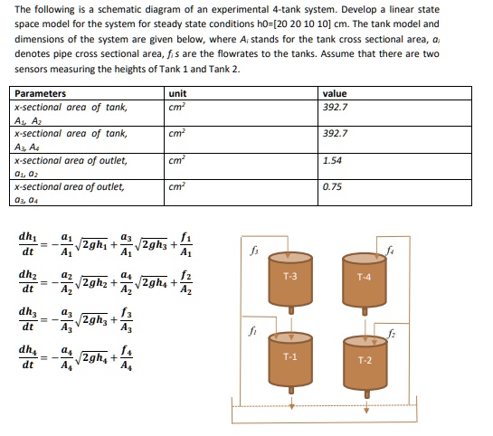
The following is a schematic diagram of an experimental 4-tank system. Develop a linear state space model for the system for steady state conditions h0=[20 20 10 10] cm. The tank model and dimensions of the system are given below, where $A_i$ stands for the tank cross sectional area, $a_i$ denotes pipe cross sectional area, $f_i$s are the flowrates to the tanks. Assume that there are two sensors measuring the heights of Tank 1 and Tank 2.
Parameters
unit
x-sectional area of tank,
cm$^2$
$A_1, A_2$
x-sectional area of tank,
cm$^2$
$A_3, A_4$
x-sectional area of outlet,
cm$^2$
$o_1, o_2$
x-sectional area of outlet,
cm$^2$
$o_3, o_4$
$\frac{dh_1}{dt} = -\frac{a_1}{A_1}\sqrt{2gh_1} + \frac{a_3}{A_1}\sqrt{2gh_3} + \frac{f_1}{A_1}$
$\frac{dh_2}{dt} = -\frac{a_2}{A_2}\sqrt{2gh_2} + \frac{a_4}{A_2}\sqrt{2gh_4} + \frac{f_2}{A_2}$
$\frac{dh_3}{dt} = -\frac{a_3}{A_3}\sqrt{2gh_3} + \frac{f_3}{A_3}$
$\frac{dh_4}{dt} = -\frac{a_4}{A_4}\sqrt{2gh_4} + \frac{f_4}{A_4}$