This circuit shown in Figure 1 is an implementation of the summation expression. Note that the numbers indicated in the summation expression are the inputs to the multiplexer that are tied to a logic 1. The remaining inputs are tied to a logic 0. When used in this configuration, the multiplexer will act as a "rotary switch", to provide the value on the addressed D input on the Q output. Therefore, if $ABC = 000$, the input on $D_0$ will be present on the output of the multiplexer. According to our summation expression, 0 is one of the summed values, and it has been tied to a logic 1.
Part 1: Design and test a circuit that uses an SN74151 multiplexer to implement a sum-of-products expression.
Step 1: Convert the logic expression to summation form (SOP):
$Y = f(A, B, C) = AB + BC$
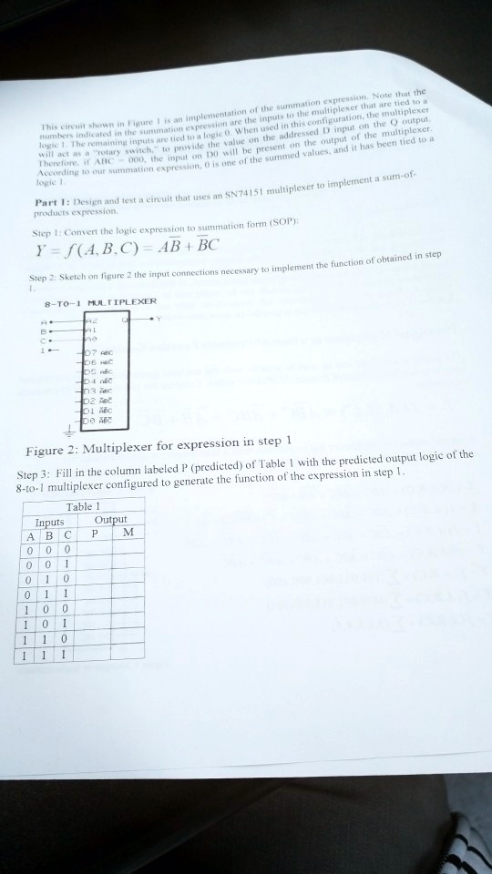
Step 2: Sketch on figure 2 the input connections necessary to implement the function of obtained in step 1.
8-TO-1 MULTIPLEXER
Figure 2: Multiplexer for expression in step 1
Step 3: Fill in the column labeled P (predicted) of Table 1 with the predicted output logic of the 8-to-1 multiplexer configured to generate the function of the expression in step 1.
Inputs Output
Table 1
ABC
P
M
0 0 0
0 0 1
0 1 0
0 1 1
1 0 0
1 0 1
1 1 0
1 1 1