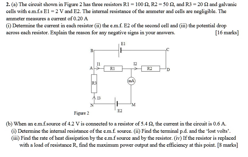
2. (a) The circuit shown in Figure 2 has three resistors R1 = 100 Ω, R2 = 50 2, and R3 = 20 2 and galvanic
cells with e.m.f.s E1 = 2 V and E2. The internal resistance of the ammeter and cells are negligible. The
ammeter measures a current of 0.20 A
(i) Determine the current in each resistor (ii) the e.m.f. E2 of the second cell and (iii) the potential drop
across each resistor. Explain the reason for any negative signs in your answers.
[16 marks]
B
E1
C
11
12
A
R1
R2
D
R3
13
N
(mA
M
E2
Figure 2
(b) When an e.m.f.source of 4.2 V is connected to a resistor of 5.4 2, the current in the circuit is 0.6 A.
(i) Determine the internal resistance of the e.m.f. source. (ii) Find the terminal p.d. and the 'lost volts'.
(iii) Find the rate of heat dissipation by the e.m.f source and by the resistor. (iv) If the resistor is replaced
with a load of resistance R, find the maximum power output and the efficiency at this point. [8 marks]