Design a 4-bit adder-subtractor using the minimum number of full adders and any additional necessary logic gates. The circuit has a mode input M that controls its operation. Specifically, when M=0, the circuit becomes a 4-bit adder and when M=1, the circuit becomes a 4-bit subtractor. Specifically, consider A, B are two 4-bits binary numbers, then:
When M=0, we perform A+B, and we assume that both numbers are unsigned numbers. So, the maximum sum value will be 15 (since we are assuming A and B are 4-bit numbers).
When M=1, we perform A-B as follows:
A+(B)_(2) 'Eomplement
That is, we find first the 2's complement of B then adds it to A. Hence, here the answer of the operation A-B is expressed in 2's complement representation.
German-Jordanian University
School of Electrical Engineering and Information Technology Department of Computer Engineering
الجامعة الألمانية الأردنية
German Jordanian University
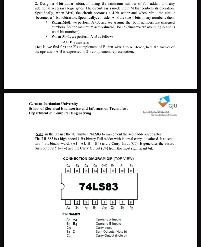
Note: in the lab use the IC number 74LS83 to implement the 4-bit adder-subtractor. The 74LS83 is a high-speed 4-Bit binary Full Adder with internal carry lookahead. It accepts two 4-bit binary words (A1- A4, B1- B4) and a Carry Input (C0). It generates the binary Sum outputs sum 1-sum 4 ) and the Carry Output (C4) from the most significant bit.
CONNFCTION MIAGRAM IIP (TOP VIFIN)
2. Design a 4-bit adder-subtractor using the minimum number of full adders and any additional necessary logic gates. The circuit has a mode input M that controls its operation. Specifically, when M=0, the circuit becomes a 4-bit adder and when M=1, the circuit becomes a 4-bit subtractor. Specifically, consider A, B are two 4-bits binary numbers, then When M=0.we perform A+B. and we assume that both numbers are unsigned numbers. So, the maximum sum value will be 15 (since we are assuming A and B are 4-bit numbers). When M=1, we perform A-B as follows: A+ (B)2Complement That is, we find first the 2s complement of B then adds it to A. Hence, here the answer of the operation A-B is expressed in 2s complement representation
German-Jordanian University School of Electrical Engineering and Information Technology Department of Computer Engineering
GJU
Note: in the lab use the IC number 74LS83 to implement the 4-bit adder-subtractor. The 74LS83 is a high-speed 4-Bit binary Full Adder with internal carry lookahead. It accepts two 4-bit binary words (A1 A4, B1 B4) and a Carry Input (C0). It generates the binary Sum outputs 14 and the Carry Output (C4 from the most significant bit.
CONNECTION DIAGRAM DIP(TOPVIEW)
B4 4 C4 16 15 14
Co GND B1 13 12 11
A1 21 10 9
74LS83
1
2 23
3
4
5 6 7 8 Vcc 22 B2 A2
A4
A3 B3
PIN NAMES A1-A4 B1-B4 Co 21-24 C4
Operand A Inputs Operand B Inputs Carry Input Sum Outputs (Note b) Carry Output (Note b)