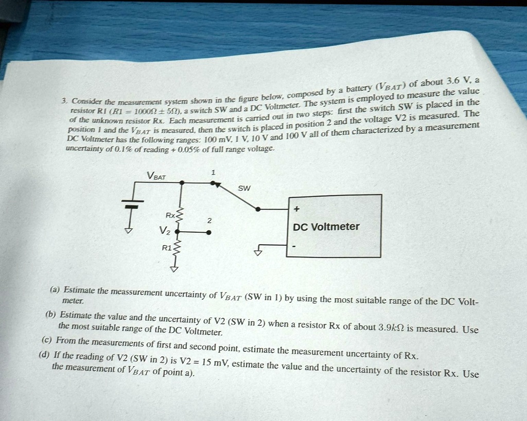
3. Consider the measurement system shown in the figure below, composed by a battery ($V_{BAT}$) of about 3.6 V, a
resistor R1 (R1 = 10000 $\pm$ 5$\Omega$), a switch SW and a DC Voltmeter. The system is employed to measure the value
of the unknown resistor Rx. Each measurement is carried out in two steps: first the switch SW is placed in the
position 1 and the $V_{BAT}$ is measured, then the switch is placed in position 2 and the voltage V2 is measured. The
DC Voltmeter has the following ranges: 100 mV, 1 V, 10 V and 100 V all of them characterized by a measurement
uncertainty of 0.1% of reading + 0.05% of full range voltage.
$V_{BAT}$
Rx
2
$V_2$
R1
1
SW
+
DC Voltmeter
(a) Estimate the measurement uncertainty of $V_{BAT}$ (SW in 1) by using the most suitable range of the DC Volt-
meter.
(b) Estimate the value and the uncertainty of V2 (SW in 2) when a resistor Rx of about 3.9k$\Omega$ is measured. Use
the most suitable range of the DC Voltmeter.
(c) From the measurements of first and second point, estimate the measurement uncertainty of Rx.
(d) If the reading of V2 (SW in 2) is V2 = 15 mV, estimate the value and the uncertainty of the resistor Rx. Use
the measurement of $V_{BAT}$ of point a).