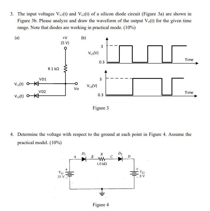
3. The input voltages $V_{i,1}(t)$ and $V_{i,2}(t)$ of a silicon diode circuit (Figure 3a) are shown in
Figure 3b. Please analyze and draw the waveform of the output $V_o(t)$ for the given time
range. Note that diodes are working in practical mode. (10%)
(a)
+V
(b)
(5 V)
3
$V_{i,1}(V)$
0.3
R 1 k?
VD1
3
$V_{i,1}(t)$
$V_{o}$
VD2
$V_{i,2}(V)$
$V_{i,2}(t)$
0.3
Figure 3
Time
Time
4. Determine the voltage with respect to the ground at each point in Figure 4. Assume the
practical model. (10%)
$V_{SI}$
25 V
$D_1$
A
B
R
1.0 k?
$D_2$
C
D
Figure 4
$V_{S2}$
-8 V