1. Passive Sallen-Key filter
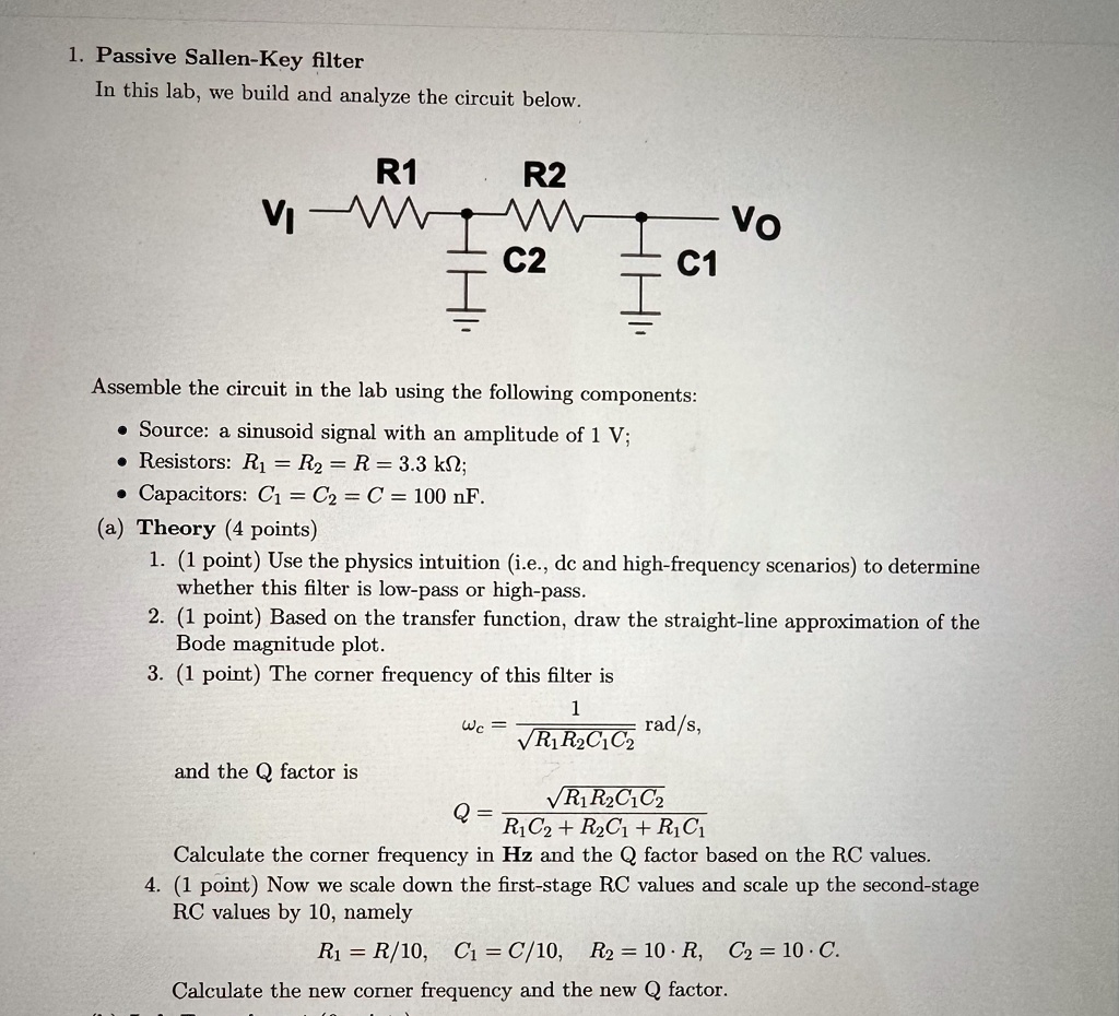
In this lab, we build and analyze the circuit below.
R1
R2
VW
C2
H
C1
Vo
Assemble the circuit in the lab using the following components:
• Source: a sinusoid signal with an amplitude of 1 V;
• Resistors: R₁ = R2 = R = 3.3 ΚΩ;
• Capacitors: C₁ = C2 = C = 100 nF.
(a) Theory (4 points)
1. (1 point) Use the physics intuition (i.e., dc and high-frequency scenarios) to determine
whether this filter is low-pass or high-pass.
2. (1 point) Based on the transfer function, draw the straight-line approximation of the
Bode magnitude plot.
3. (1 point) The corner frequency of this filter is
1
Wc =
rad/s,
√R1R2C1C2
and the Q factor is
√R1 R2C1C2
Q =
R1C2+R2C1 + R1C1
Calculate the corner frequency in Hz and the Q factor based on the RC values.
4. (1 point) Now we scale down the first-stage RC values and scale up the second-stage
RC values by 10, namely
R1R/10, C₁ = C/10, R2 = 10 R, C2 = 10. С.
Calculate the new corner frequency and the new Q factor.