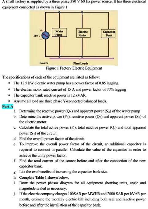
A small factory is supplied by three-phase equipment connected as shown in Figure 1.
Electric Motor
Capacitor Bank
10
Source Plant Loads Figure 1: Factory Electric Equipment
The specifications of each of the equipment are listed as follows:
- The 12.5 kW electric water pump has a power factor of 0.85 lagging.
- The electric motor has a rated current of 15 A and a power factor of 70% lagging.
- The capacitor bank has a reactive power of 12 kVAR.
Assume all loads are three-phase Y-connected balanced loads.
Part A:
a. Determine the reactive power (Q) and apparent power (S) of the water pump.
b. Determine the active power (P), reactive power (Qn), and apparent power (S) of the electric motor.
c. Calculate the total active power (P), total reactive power (Q), and total apparent power (Sr) of the circuit.
d. Find the overall power factor of the circuit.
To improve the overall power factor of the circuit, an additional capacitor is required to be connected in parallel. Calculate the value of the capacitor in order to achieve unity power factor.
f. Find the total current of the source before and after the connection of the new capacitor bank.
g. List the two benefits of increasing the capacitor bank size.
h. Complete Table 1 shown below.
Draw the power phasor diagram for all equipment, showing units, angle, and magnitude scaled as necessary.
j. If the electric company charges 100 SAR per MWh and 2000 SAR per kVAR per month, estimate the monthly electric bill including both real and reactive power before and after the installation of the capacitor bank.