I was curious if somebody can show me how this looks on an actual breadboard? I have broken 3 relays trying so far!
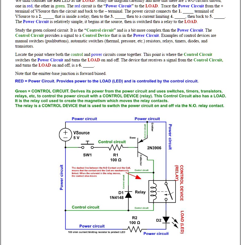
One in red, the other in green. The red circuit is the Power Circuit to the LOAD. Trace the Power Circuit from the + terminal of VSource through the circuit and back to the terminal. The power circuit connects the 1st terminal of VSource to a 2nd that is inside a relay, then to the 3rd, then to a current limiting 4th, then back to the 5th. The Power Circuit is relatively simple, it begins at the source, then is switched through a relay to the LOAD.
Study the green colored circuit. It is the Control circuit and is a bit more complex than the Power Circuit. The Control Circuit provides a signal to a Control Device that is in the Power Circuit. Examples of control devices are manual switches (pushbuttons), automatic switches (thermal, pressure, etc.), resistors, relays, timers, diodes, and transistors.
Locate the point where both the control and power circuits come together. This point is where the Control Circuit switches the Power Circuit and turns the LOAD on and off. The device that receives a signal from the Control Circuit, and turns the LOAD on and off, is a 6th.
Note that the emitter-base junction is forward biased.
RED = Power Circuit. Provides power to the LOAD (LED) and is controlled by the control circuit.
Green = CONTROL CIRCUIT. Derives its power from the power circuit and uses switches, timers, transistors, relays, etc., to control the power circuit with a CONTROL DEVICE (relay). This Control Circuit also has a LOAD. It is the relay coil used to create the magnetism which moves the relay contacts. The relay is a CONTROL DEVICE that is used to switch the power circuit on and off via the N.O. relay contact.
Power circuit
Power circuit Emitter VSource 5V Power circuit Control circuit WWM 2N3906 SW1 R1 100 ohm resistor The dashed line between the N.O Contact and the Coil, linked. When the solenoid in the relay moves means that the contact and the Coil are mechanical Control circuit (RELAY) Power circuit CONTROL DEVICE D1 Relay 1N4148 Control circuit Control circuit R2 100 ohm D2 LOAD (LED) Power circuit 100 ohm current limiting resistor to protect LED Power circuit