Ace - AI Tutor
Ask Our Educators
Textbooks
My Library
Flashcards
Scribe - AI Notes
Notes & Exams
Download App
Mohammed Ahmed

Mohammed A.

Divider

Viewed Questions

Explain the difference between fast computing and real-time computing.

Hard Real-Time Computing Systems (The International Series in Engineering and Computer Science)

Questions asked

ANSWERED

Aparna Shakti verified

Numerade educator

Example 2.9 Figure 2.34 For Example 2.9.

View Answer
divider
ANSWERED

Melissa Munoz verified

Numerade educator

Three light bulbs are connected to a 9-V battery as shown in Fig. 2.56(a). Example 2.16 Calculate: (a) the total current supplied by the battery, (b) the current through each bulb, (c) the resistance of each bulb. Figure 2.56 (a) Lighting system with three bulbs, (b) resistive circuit equivalent model.

View Answer
divider
ANSWERED

Bcrypt_Sha256$$2B$12$We1Wwocamog01O5I.V2Tkouxdh4Ofnmgpwkor7Leaonfpu0Ubfpua Bcrypt_Sha256$$2B$12$We1Wwocamog01O5I.V2Tkokttmmj7Lscvwvlptp4Rlhbswcdg9.Wy verified

Numerade educator

Find v1 and v2 in the circuit shown in Fig. 2.43. Also calculate i1 and i2 and the power dissipated in the 12-? and 40-? resistors. Answer: v1 = 10 V, i1 = 833.3 mA, p1 = 8.333 W, v2 = 20 V, i2 = 500 mA, p2 = 10 W. Practice Problem 2.12 Figure 2.43 For Practice Prob. 2.12.

View Answer
divider
ANSWERED

Melissa Munoz verified

Numerade educator

Find ( R_{a b} ) for the circuit in Fig. 2.39. Practice Problem 2.10 Answer: ( 19 Omega ). Figure 2.39 For Practice Prob. 2.10.

View Answer
divider
ANSWERED

Nishant Kumar verified

Numerade educator

Example 2.9 Figure 2.34 For Example 2.9.

View Answer
divider
INSTANT ANSWER

Let's design a circuit that produces a \( 5-\mathrm{V} \) output from a \( 12-\mathrm{V} \) input. We will arbitrarily fix the power consumed by the circuit at 240 mW . Finally, we will choose the best possible standard resistor values from Table 2.1 and calculate the percent error in the output voltage that results from that choice. 
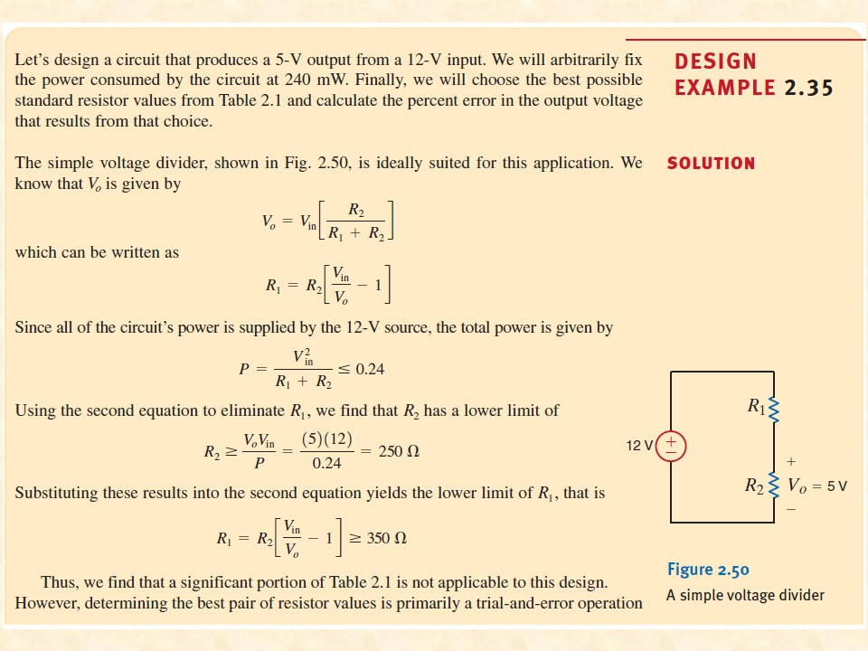
The simple voltage divider, shown in Fig. 2.50, is ideally suited for this application. We know that \( V_{o} \) is given by \[ V_{o}=V_{\text {in }}\left[\frac{R_{2}}{R_{1}+R_{2}}\right] \] which can be written as \[ R_{1}=R_{2}\left[\frac{V_{\text {in }}}{V_{o}}-1\right] \] Since all of the circuit's power is supplied by the \( 12-\mathrm{V} \) source, the total power is given by \[ P=\frac{V_{\text {in }}^{2}}{R_{1}+R_{2}} \leq 0.24 \] Using the second equation to eliminate \( R_{1} \), we find that \( R_{2} \) has a lower limit of \[ R_{2} \geq \frac{V_{o} V_{\text {in }}}{P}=\frac{(5)(12)}{0.24}=250 \Omega \] Substituting these results into the second equation yields the lower limit of \( R_{1} \), that is \[ R_{1}=R_{2}\left[\frac{V_{\mathrm{in}}}{V_{o}}-1\right] \geq 350 \Omega \] Thus, we find that a significant portion of Table 2.1 is not applicable to this design. However, determining the best pair of resistor values is primarily a trial-and-error operation DESIGN EXAMPLE 2.35 SOLUTION

View Answer
divider
ANSWERED

Eduard Sanchez verified

Numerade educator

Current Division i1(t) = v(t) / R1 = R2 / (R1 + R2) * i(t) i2(t) = v(t) / R2 = R1 / (R1 + R2) * i(t) v(t) = Rp * i(t) = (R1 * R2) / (R1 + R2) * i(t) Current divides in inverse proportion to the resistances

View Answer
divider
ANSWERED

Bcrypt_Sha256$$2B$12$We1Wwocamog01O5I.V2Tkouxdh4Ofnmgpwkor7Leaonfpu0Ubfpua Bcrypt_Sha256$$2B$12$We1Wwocamog01O5I.V2Tkokttmmj7Lscvwvlptp4Rlhbswcdg9.Wy verified

Numerade educator

Parallel Resistors I = I_1 + I_2 = V/R_1 + V/R_2 = V(1/R_1 + 1/R_2) = V/R_p 1/R_p = 1/R_1 + 1/R_2 R_p = (R_1*R_2) / (R_1 + R_2) 1/R_eq = 1/R_1 + 1/R_2 + ... + 1/R_N Note that R_eq is always smaller than the resistance of the smallest resistor in the parallel combination. If R_1 = R_2 = ... = R_N = R, then R_eq = R / N G_eq = G_1 + G_2 + G_3 + ... + G_N

View Answer
divider
ANSWERED

Eduard Sanchez verified

Numerade educator

Voltage Divider Find the current and branch voltages I = V0 / Rs = V0 / (R1 + R2) V2 = IR2 = (V0 / (R1 + R2)) * R2 V2 = (R2 / (R1 + R2)) * V0 V1 = (R1 / (R1 + R2)) * V0

View Answer
divider
ANSWERED

Eduard Sanchez verified

Numerade educator

Series Resistors For N resistors in series then, Req = R1 + R2 + ... + RN = sum(n=1 to N) Rn 1/Geq = 1/G1 + 1/G2 + 1/G3 + ... + 1/GN V0 = V1 + V2 = IR1 + IR2 = I(R1 + R2) = IRs Rs = R1 + R2

View Answer
divider