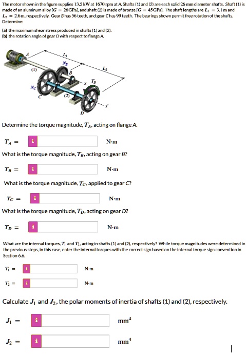
The motor shown in the figure supplies 13.5 kW at 1670 rpm at A. Shafts (1) and (2) are each solid 26 mm diameter shafts. Shaft (1) is
made of an aluminum alloy [G = 26GPa], and shaft (2) is made of bronze [G = 45GPa]. The shaft lengths are L₁ = 3.1 m and
L₂ = 2.6 m, respectively. Gear B has 56 teeth, and gear C has 99 teeth. The bearings shown permit free rotation of the shafts.
Determine:
(a) the maximum shear stress produced in shafts (1) and (2).
(b) the rotation angle of gear D with respect to flange A.
Determine the torque magnitude, $T_A$, acting on flange A.
$T_A$ = i N-m
What is the torque magnitude, $T_B$, acting on gear B?
$T_B$ = i N-m
What is the torque magnitude, $T_C$, applied to gear C?
$T_C$ = i N-m
What is the torque magnitude, $T_D$, acting on gear D?
$T_D$ = i N-m
What are the internal torques, $T_1$ and $T_2$, acting in shafts (1) and (2), respectively? While torque magnitudes were determined in
the previous steps, in this case, enter the internal torques with the correct sign based on the internal torque sign convention in
Section 6.6.
$T_1$ = i N-m
$T_2$ = i N-m
Calculate $J_1$ and $J_2$, the polar moments of inertia of shafts (1) and (2), respectively.
$J_1$ = i $mm^4$
$J_2$ = i $mm^4$