How do you calculate the magnitude again?
Help with all would be ideal.
Each student must submit his/her own pre-lab and lab report, unless otherwise indicated. Pre-lab (Please use the Answer Sheet, available on Blackboard):
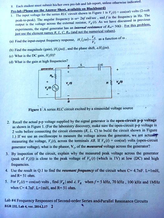
1. The input voltage for the series RLC circuit shown in Figure 1 is V = cos(θ) volts, 2-volt peak-to-peak. The angular frequency is ω = 2 rad/sec, and f is the frequency in Hz. The output is the voltage across the external resistor, V. As we have discussed in previous experiments, the signal generator has an internal resistance of R = 50 Ω. For this problem, just use the element names R, L, C, and R (and not the numerical values).
a. Find the magnitude gain, H, and the phase shift, θ.
b. What is the DC gain, H0?
c. What is the gain at high frequencies?
Figure 1: A series RLC circuit excited by a sinusoidal voltage source.
2. Recall that the actual peak-to-peak voltage supplied by the signal generator is the open-circuit peak-to-peak voltage as shown in Figure 1. (For the laboratory discovery, make sure the open-circuit peak-to-peak voltage is 2 volts before connecting the circuit elements (R, L, C) to build the circuit shown in Figure 1). If we use an oscilloscope to measure the voltage across the generator, we are actually measuring the voltage, V, across the terminals AB. If V = cos(θ) volts is the open-circuit generator voltage, what is the phasor, V, of the measured voltage across the generator?
3. By inspection of the circuit, explain why the measured peak voltage across the generator (peak of V) is close to the peak voltage of Vs (which is 2V) at low DC and high frequencies.
4. Use the result in Q.1 to find the resonant frequency of the circuit when C = 4.7nF, L = 1mH, and R = 51Ω.
5. For V = cos(θ) volts, find |V| and |Vg| when f = 5 kHz, 70 kHz, 100 kHz, and 1 MHz, when C = 4.7nF, L = 1mH, and R = 51Ω.
Lab #4: Frequency Responses of Second-order Series and Parallel Resonance Circuits EGR 232, Lab 4.ver.2014.2.172