2. Voltage Controlled Voltage Source
R1
4 ??
I2
6 ??
R2
+
Vi
10V
V2
R2
6 ??
3V
Vo
R4
3??
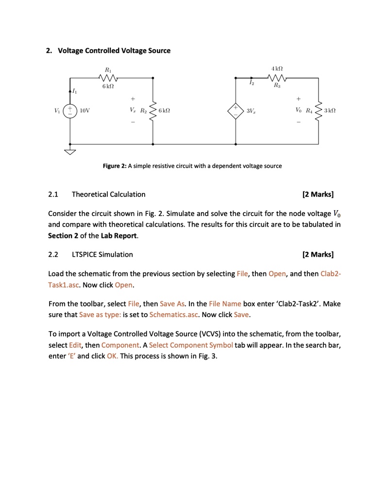
Figure 2: A simple resistive circuit with a dependent voltage source
2.1 Theoretical Calculation
[2 Marks]
Consider the circuit shown in Fig. 2. Simulate and solve the circuit for the node voltage V$_o$
and compare with theoretical calculations. The results for this circuit are to be tabulated in
Section 2 of the Lab Report.
2.2
LTSPICE Simulation
[2 Marks]
Load the schematic from the previous section by selecting File, then Open, and then Clab2-
Task1.asc. Now click Open.
From the toolbar, select File, then Save As. In the File Name box enter 'Clab2-Task2'. Make
sure that Save as type: is set to Schematics.asc. Now click Save.
To import a Voltage Controlled Voltage Source (VCVS) into the schematic, from the toolbar,
select Edit, then Component. A Select Component Symbol tab will appear. In the search bar,
enter 'E' and click OK. This process is shown in Fig. 3.