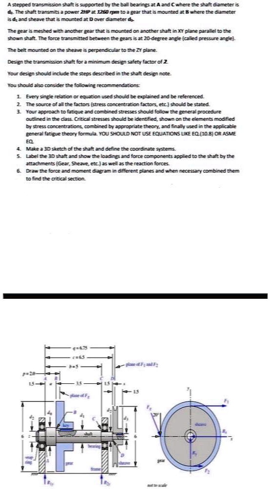
A stepped transmission shaft is supported by the ball bearings at A and C where the shaft diameter is
d. The shaft transmits a power 2HP at 1260 rpm to a gear that is mounted at B where the diameter
is d, and sheave that is mounted at D over diameter d
The gear is meshed with another gear that is mounted on another shaft in XY plane parallel to the
shown shaft. The force transmitted between the gears is at 20-degree angle (called pressure angle).
The belt mounted on the sheave is perpendicular to the ZY plane.
Design the transmission shaft for a minimum design safety factor of 2.
Your design should include the steps described in the shaft design note.
You should also consider the following recommendations:
1. Every single relation or equation used should be explained and be referenced.
2. The source of all the factors (stress concentration factors, etc.) should be stated.
3. Your approach to fatique and combined stresses should follow the general procedure
outlined in the class. Critical stresses should be identified, shown on the elements modified
by stress concentrations, combined by appropriate theory, and finally used in the applicable
general fatigue theory formula. YOU SHOULD NOT USE EQUATIONS LIKE EQ. (10.8) OR ASME
EQ
4. Make a 3D sketch of the shaft and define the coordinate systems.
5. Label the 3D shaft and show the loadings and force components applied to the shaft by the
attachments (Gear, Sheave, etc.) as well as the reaction forces.
6. Draw the force and moment diagram in different planes and when necessary combined them
to find the critical section.