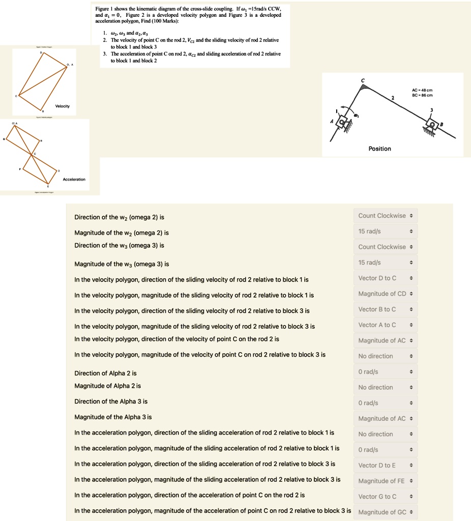
Figure 1 shows the kinematic diagram of the cross-slide coupling. If w₁ =15rad/s CCW,
and a₁=0, Figure 2 is a developed velocity polygon and Figure 3 is a developed
acceleration polygon, Find (100 Marks):
1. ω, ω and a₂, a
2. The velocity of point C on the rod 2, Vc₂ and the sliding velocity of rod 2 relative
to block 1 and block 3
3. The acceleration of point C on rod 2, ac₂ and sliding acceleration of rod 2 relative
to block 1 and block 2
Velocity
Acceleration
Position
AC = 48 cm
BC = 86 cm
Direction of the w₂ (omega 2) is
Magnitude of the w₂ (omega 2) is
Direction of the w3 (omega 3) is
Magnitude of the w3 (omega 3) is
In the velocity polygon, direction of the sliding velocity of rod 2 relative to block 1 is
In the velocity polygon, magnitude of the sliding velocity of rod 2 relative to block 1 is
In the velocity polygon, direction of the sliding velocity of rod 2 relative to block 3 is
In the velocity polygon, magnitude of the sliding velocity of rod 2 relative to block 3 is
In the velocity polygon, direction of the velocity of point C on the rod 2 is
In the velocity polygon, magnitude of the velocity of point C on rod 2 relative to block 3 is
Direction of Alpha 2 is
Magnitude of Alpha 2 is
Direction of the Alpha 3 is
Magnitude of the Alpha 3 is
In the acceleration polygon, direction of the sliding acceleration of rod 2 relative to block 1 is
In the acceleration polygon, magnitude of the sliding acceleration of rod 2 relative to block 1 is
In the acceleration polygon, direction of the sliding acceleration of rod 2 relative to block 3 is
In the acceleration polygon, magnitude of the sliding acceleration of rod 2 relative to block 3 is
In the acceleration polygon, direction of the acceleration of point C on the rod 2 is
In the acceleration polygon, magnitude of the acceleration of point C on rod 2 relative to block 3 is