Please simulate the circuit, and fill out the tables. Will upvote, thanks.
Table 2.3:
5. Put a 10F capacitor in parallel with RL. Repeat step 4.
6. Repeat step 4 for C = 22F and 47F. Record V = and Vmin in Table 2.4 for each configuration from steps 4, 5, and 6, and compute Vrms, V, and ripple factor RF.
S. Use RL = 100k, C = 47uF. Note the output waveform. Put a 1k resistor in parallel with Ri and note the change in the output wave shape.
PART II FULL-WAVE RECTIFIER & POWER SUPPLY
Table 2.4: RF at various C when RL = 1k
R = 1k; Cf No Capacitor 10 22 47
Vm
Vmin
V
V(rms)
Vac
Ripple Factor
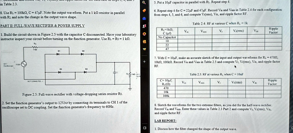
1. Build the circuit shown in Figure 2.5 with the capacitor C disconnected. Have your laboratory instructor inspect your circuit before turning on the function generator. Use Ri = Rs = 1k RS W D1.
7. With C = 10F, make an accurate sketch of the input and output waveforms for R = 470 10k, 100k. Record Vm and Vmin in Table 2.5 and compute Vr, Vr(rms), V, and ripple factor RF.
Table 2.5: RF at various R when C = 10uF
C = 10f; R) 470 10k 100k
Vm
Vmin
V
V(rms)
Vac
Ripple Factor
Figure 2.5: Full-wave rectifier with voltage-dropping series resistor Rs.
2. Set the function generator's output to 12Vp by connecting its terminals to CH 1 of the oscilloscope set to DC coupling. Set the function generator's frequency to 60Hz.
3. Sketch the waveforms for the two extreme filters, as you did for the half-wave rectifier. Record Vm and V=in. Enter these values in Table 2.3 Part 2 and compute Vr, Vrms, V&c, and ripple factor RF.
LAB REPORT:
1. Discuss how the filter changed the shape of the output wave.