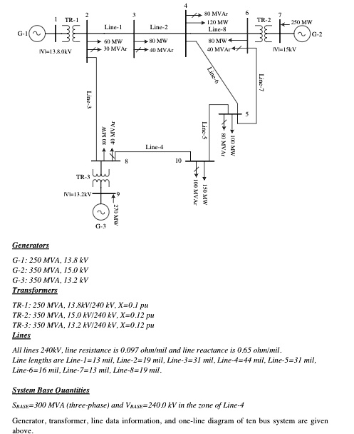
Would you explain step by step how to simulate this circuit on PowerWorld Simulator?
If you share your work as a pwb file, that would be appreciated.
The due date is tomorrow for the assignment.
3
80 MVAr 120 MW Line-8 80 MW 4 40 MVAr
BELO Line-1 60 MW IV=13.8.0kV > 30 MVAr
Line-2
TR-2
50 MW
> 80 MW > 40 MVAr
IV=15kV
Line-7
Line-3
MW 08
Line-5 Line-4 80 MVAr > 100 MW 10
TR-3 33 IV=13.2kV
150 MW
G-3
Generators G-1: 250 MVA, 13.8 kV G-2: 350 MVA, 15.0 kV G-3: 350 MVA, 13.2 kV Transformers
TR-1: 250 MVA, 13.8 kV/240 kV, X=0.1 pu TR-2: 350 MVA, 15.0 kV/240 kV, X=0.12 pu TR-3: 350 MVA, 13.2 kV/240 kV, X=0.12 pu Lines
All lines 240 kV, line resistance is 0.097 ohm/mil, and line reactance is 0.65 ohm/mil. Line lengths are Line-1=13 mil, Line-2=19 mil, Line-3=31 mil, Line-4=44 mil, Line-5=31 mil, Line-6=16 mil, Line-7=13 mil, Line-8=19 mil
System Base Quantities SgAsE=300 MVA (three-phase) and VgASE=240.0 kV in the zone of Line-4
Generator, transformer, line data information, and one-line diagram of a ten-bus system are given above