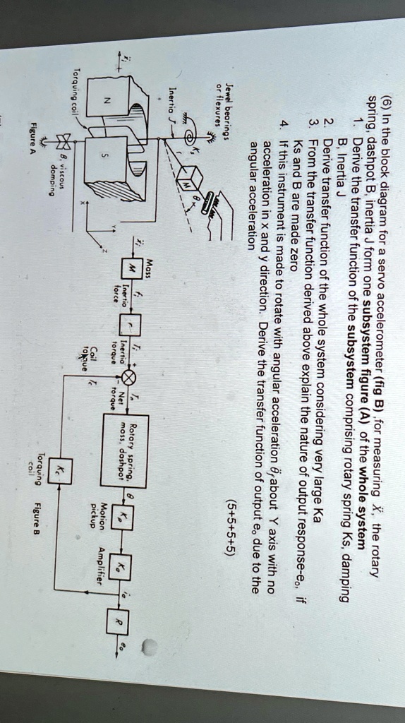
(6) In the block diagram for a servo accelerometer (fig B), for measuring x^(¨), the rotary spring, dashpot B, inertia J form one subsystem figure (A) of the whole system.
Derive the transfer function of the subsystem comprising rotary spring Ks, damping B, Inertia J.
Derive the transfer function of the whole system considering very large Ka.
From the transfer function derived above, explain the nature of output response - e_(0), if Ks and B are made zero.
If this instrument is made to rotate with angular acceleration θ_(f)^(¨) about Y axis with no acceleration in x and y direction, derive the transfer function of output e_(o) due to the angular acceleration.
Torquing coil N 1.
Figure A: Inertia J - or flexures, Jewel bearings 3 2 damping angular acceleration Ks and B are made zero B, Inertia J - ofce Mass 1ok7ue Coil torque Inertia acceleration in x and y direction. Derive the transfer function of output e, due to the If this instrument is made to rotate with angular acceleration & about Y axis with no Derive transfer function of the whole system considering very large Ka spring, dashpot B, inertia J form one subsystem figure (A) of the whole system torau Ne From the transfer function derived above explain the nature of output response - eo, if Derive the transfer function of the subsystem comprising rotary spring Ks, damping coil Torquing Ke moss, dashpot Rotary spring. Figure B pickup Motion Amplifier 5+5+5+5