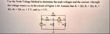
Use the Node Voltage Method to determine the node voltages and the current $i$ through the voltage source $v_{S2}$ in the circuit of Figure 1.64. Assume that $R_1 = 2\Omega$, $R_2 = 2\Omega$, $R_3 = 4\Omega$, $R_4 = 3\Omega$, $v_{S1} = 2$ V, and $v_{S2} = 3$ V.