6. Experimental circuit design
6.1 Resistor color code
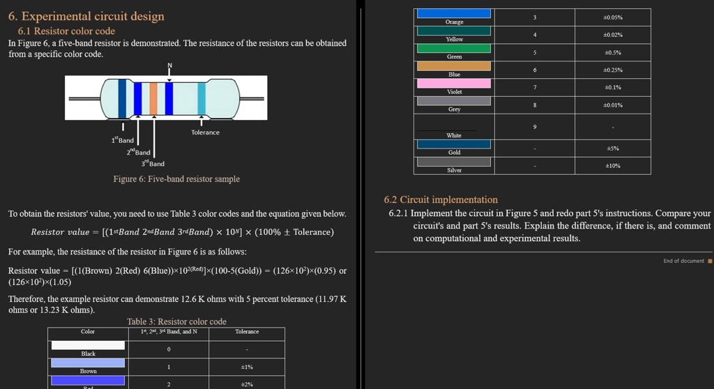
In Figure 6, a five-band resistor is demonstrated. The resistance of the resistors can be obtained
from a specific color code.
1"Band
2nd Band
3d Band
Tolerance
Orange
±0.05%
Yellow
±0.02%
Green
±0.5%
Blue
±0.25%
Violet
±0.1%
Grey
±0.01%
White
Gold
Silver
±5%
±10%
Figure 6: Five-band resistor sample
To obtain the resistors' value, you need to use Table 3 color codes and the equation given below.
Resistor value = [(1stBand 2nd Band 3rd Band) × 10N] × (100% ± Tolerance)
For example, the resistance of the resistor in Figure 6 is as follows:
Resistor value = [(1(Brown) 2(Red) 6(Blue))×102(Red)]×(100-5(Gold)) = (126×102)×(0.95) or
(126×102)×(1.05)
Therefore, the example resistor can demonstrate 12.6 K ohms with 5 percent tolerance (11.97 K
ohms or 13.23 K ohms).
Color
Table 3: Resistor color code
1, 2nd, 3rd Band, and N
Tolerance
6.2 Circuit implementation
6.2.1 Implement the circuit in Figure 5 and redo part 5's instructions. Compare your
circuit's and part 5's results. Explain the difference, if there is, and comment
on computational and experimental results.
End of document