Question 7.
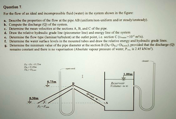
For the flow of an ideal and incompressible fluid (water) in the system shown in the figure:
a. Describe the properties of the flow at the pipe AB (uniform/non-uniform and/or steady/unsteady).
b. Compute the discharge (Q) of the system.
c. Determine the mean velocities at the sections A, B, and C of the pipe.
d. Draw the relative hydraulic grade line (piezometer line) and energy line of the system
e. Determine the flow type (laminar/turbulent) at the outlet point, i.e. section C ($\nu_{water}$=10$^{-6}$ m$^2$/s).
f. Determine the water surface levels in the mounted tubes and draw the relative energy and hydraulic grade lines.
g. Determine the minimum value of the pipe diameter at the section B ($D_B$=$D_{B,2}$=$D_{B,min}$), provided that the discharge (Q)
remains constant and there is no vaporisation (Absolute vapour pressure of water, $P_{vw}$, is 2.45 kN/m$^2$).
$D_A$ = $D_C$ = 0.25 m
$D_{B,2}$ = 0.20 m
$D_{B,1}$ = $D_{B,min}$