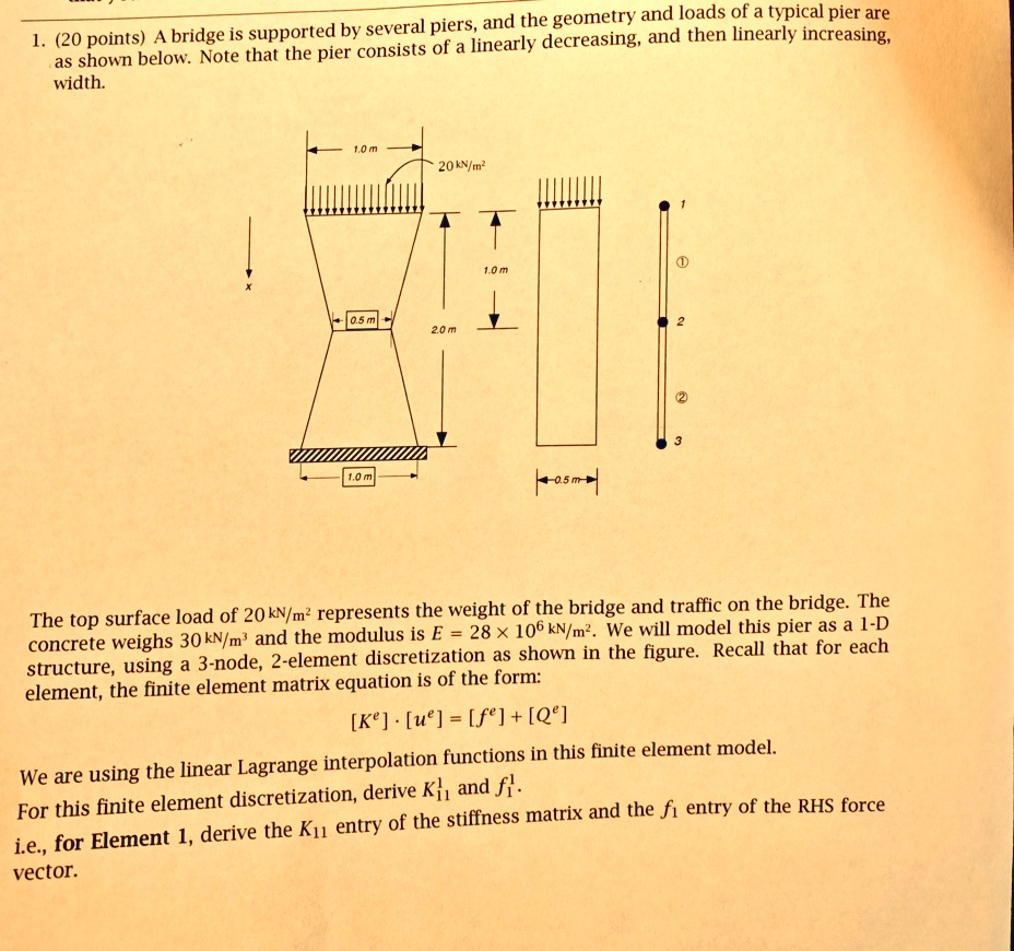
1. (20 points) A bridge is supported by several piers, and the geometry and loads of a typical pier are
as shown below. Note that the pier consists of a linearly decreasing, and then linearly increasing,
width.
1.0 m
20 kN/m²
0.5 m
2.0 m
1
①
1.0 m
1.0 m
0.5 m
2
②
3
The top surface load of 20 kN/m² represents the weight of the bridge and traffic on the bridge. The
concrete weighs 30 kN/m³ and the modulus is E = 28 × 10⁶ kN/m². We will model this pier as a 1-D
structure, using a 3-node, 2-element discretization as shown in the figure. Recall that for each
element, the finite element matrix equation is of the form:
[K] [u] = [fe] + [Q]
We are using the linear Lagrange interpolation functions in this finite element model.
For this finite element discretization, derive K₁₁ and f₁.
i.e., for Element 1, derive the K₁₁ entry of the stiffness matrix and the f₁ entry of the RHS force
vector.