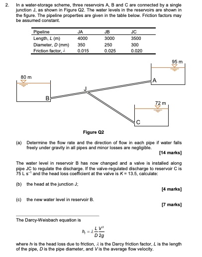
2. In a water-storage scheme, three reservoirs A, B and C are connected by a single
junction J, as shown in Figure Q2. The water levels in the reservoirs are shown in
the figure. The pipeline properties are given in the table below. Friction factors may
be assumed constant.
80 m
Pipeline
Length, L (m)
Diameter, D (mm)
Friction factor, $\lambda$
JA
JB
JC
4000
3000
3500
350
250
300
0.015
0.025
0.020
95 m
B
J
C
A
72 m
Figure Q2
(a) Determine the flow rate and the direction of flow in each pipe if water falls
freely under gravity in all pipes and minor losses are negligible.
[14 marks]
The water level in reservoir B has now changed and a valve is installed along
pipe JC to regulate the discharge. If the valve-regulated discharge to reservoir C is
75 L s?¹ and the head loss coefficient at the valve is K = 13.5, calculate:
(b) the head at the junction J;
(c) the new water level in reservoir B.
[4 marks]
[7 marks]
The Darcy-Weisbach equation is
$h_f = \lambda \frac{L}{D} \frac{V^2}{2g}$
where $h_f$ is the head loss due to friction, $\lambda$ is the Darcy friction factor, L is the length
of the pipe, D is the pipe diameter, and V is the average flow velocity.