Title: Digital Circuit Analysis and 7-Segment Display Connection
Time Slot: 9:00 am - 2:00 pm, 12:00 pm - 3:00 pm, Monday to Friday
2:59 pm - 5:59 pm, 5:39 pm - 8:30 pm
Please attempt all problems below. Half of your grade for this assignment will be based on your performance.
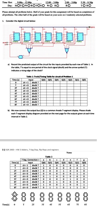
Consider the digital circuit below:
a) Record the predicted output of the circuit for the inputs provided by each row of Table 1. In the table, "T" is equal to one period of the clock signal (Tc) and the arrow symbol (→) indicates a rising edge of the clock.
Table 1:
| Time (Tc) | CE | Q1 | TQ0 | ST |
|-----------|----|----|-----|----|
| 0 | 0 | 0 | 0 | 0 |
| 1 | 1 | 0 | 1 | 0 |
| 2 | 1 | 1 | 1 | 0 |
| 3 | 0 | 1 | 0 | 1 |
| 4 | 1 | 0 | 0 | 1 |
| 5 | 0 | 0 | 1 | 1 |
| 6 | 1 | 1 | 1 | 1 |
| 7 | 0 | 1 | 0 | 0 |
b) We now connect the output bus (Q) to a common Anode 7-segment display. Please shade each 7-segment display at each time interval in Table 2.
Table 2:
| Time (s) | 7-Seg Connected |
|----------|-----------------|
| 0 | 0 |
| 3T | 0 |
| 6T | 0 |
| 7T | 0 |