Pre-laboratory Assignment:
Read the previously distributed handout on 'Oscilloscope Fundamentals' and the 'Function
Generator Quickguide'.
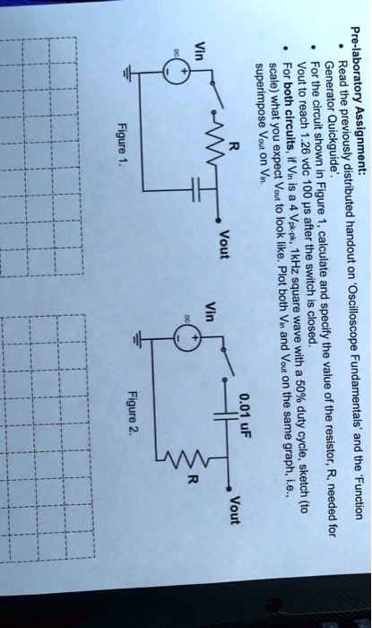
For the circuit shown in Figure 1, calculate and specify the value of the resistor, R, needed for
$V_{out}$ to reach 1.26 vdc 100 µs after the switch is closed.
For both circuits, if $V_{in}$ is a 4 $V_{pk-pk}$, 1kHz square wave with a 50% duty cycle, sketch (to
scale) what you expect $V_{out}$ to look like. Plot both $V_{in}$ and $V_{out}$ on the same graph, i.e.,
superimpose $V_{out}$ on $V_{in}$.
$V_{in}$
+
DC
R
$V_{out}$
$V_{in}$
+
DC
0.01 uF
$V_{out}$
R
Figure 1.
Figure 2.