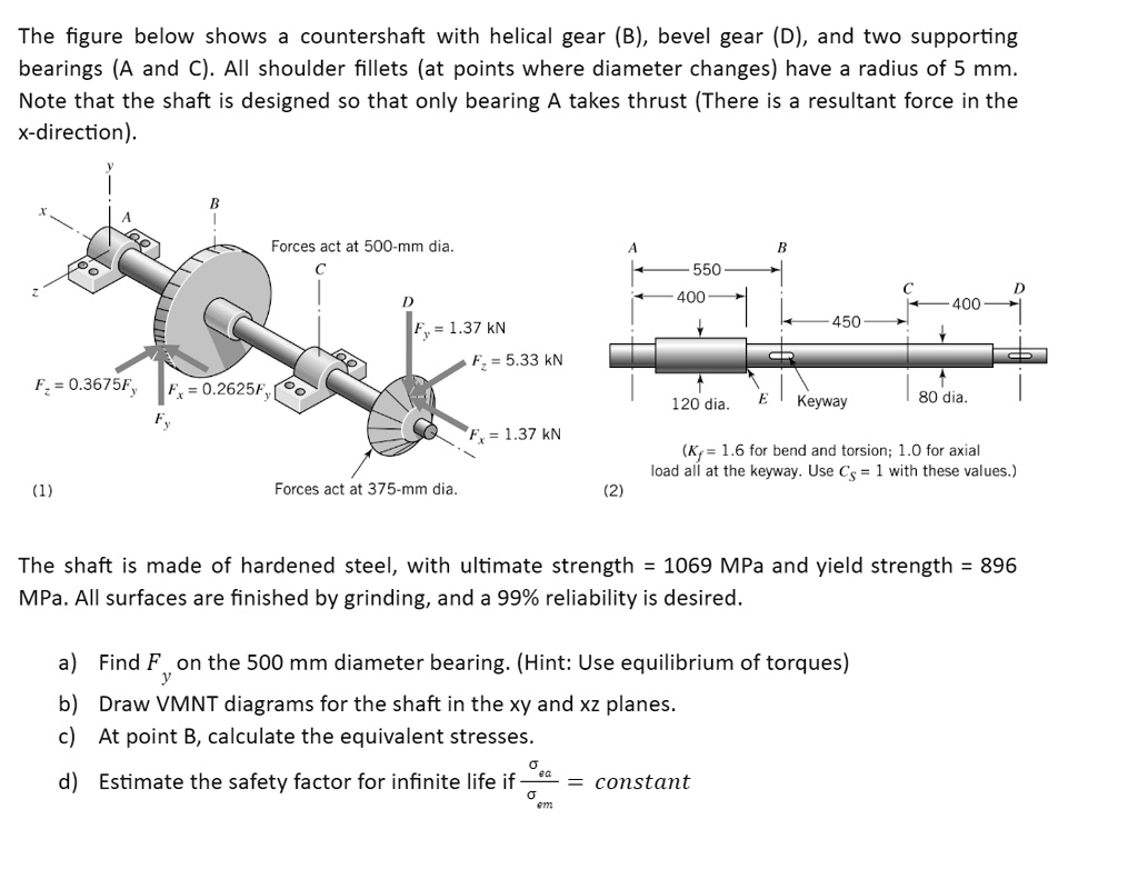
The figure below shows a countershaft with helical gear (B), bevel gear (D), and two supporting
bearings (A and C). All shoulder fillets (at points where diameter changes) have a radius of 5 mm.
Note that the shaft is designed so that only bearing A takes thrust (There is a resultant force in the
x-direction).
B
Forces act at 500-mm dia.
C
$F_x = 0.3675F_y$
$F_x = 0.2625F_y$
$F_y$
(1)
A
B
550
400
C
D
400
450
D
$F_y = 1.37 \text{ kN}$
$F_z = 5.33 \text{ kN}$
120 dia.
E
Keyway
$F_x = 1.37 \text{ kN}$
Forces act at 375-mm dia.
(2)
?
80 dia.
$(K_t = 1.6 \text{ for bend and torsion; 1.0 for axial}
\text{load all at the keyway. Use } C_s = 1 \text{ with these values.})$
The shaft is made of hardened steel, with ultimate strength = 1069 MPa and yield strength = 896
MPa. All surfaces are finished by grinding, and a 99% reliability is desired.
a) Find $F_y$ on the 500 mm diameter bearing. (Hint: Use equilibrium of torques)
b) Draw VMNT diagrams for the shaft in the xy and xz planes.
c) At point B, calculate the equivalent stresses.
d) Estimate the safety factor for infinite life if $\frac{\sigma_{eq}}{\sigma_m} = \text{constant}$