1. Consider the circuit shown in Figure 1.
Is1 R1 Is2
R2 R3
+ V
Vs1 VVF Vs2
- IF
R4 R5
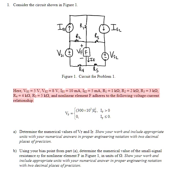
Figure 1. Circuit for Problem 1.
Here, $V_{s1} = 5$ V, $V_{s2} = 8$ V, $I_{s1} = 10$ mA, $I_{s2} = 5$ mA, $R_1 = 1$ k$\Omega$, $R_2 = 2$ k$\Omega$, $R_3 = 3$ k$\Omega$,
$R_4 = 4$ k$\Omega$, $R_5 = 5$ k$\Omega$, and nonlinear element F adheres to the following voltage-current
relationship:
$V_F = \begin{cases} (300 \times 10^3) I_F^2, & I_F > 0\\ 0, & I_F \le 0. \end{cases}$
a) Determine the numerical values of $V_F$ and $I_F$. Show your work and include appropriate
units with your numerical answers in proper engineering notation with two decimal
places of precision.
b) Using your bias point from part (a), determine the numerical value of the small-signal
resistance $r_f$ for nonlinear element F in Figure 1, in units of $\Omega$. Show your work and
include appropriate units with your numerical answer in proper engineering notation
with two decimal places of precision.