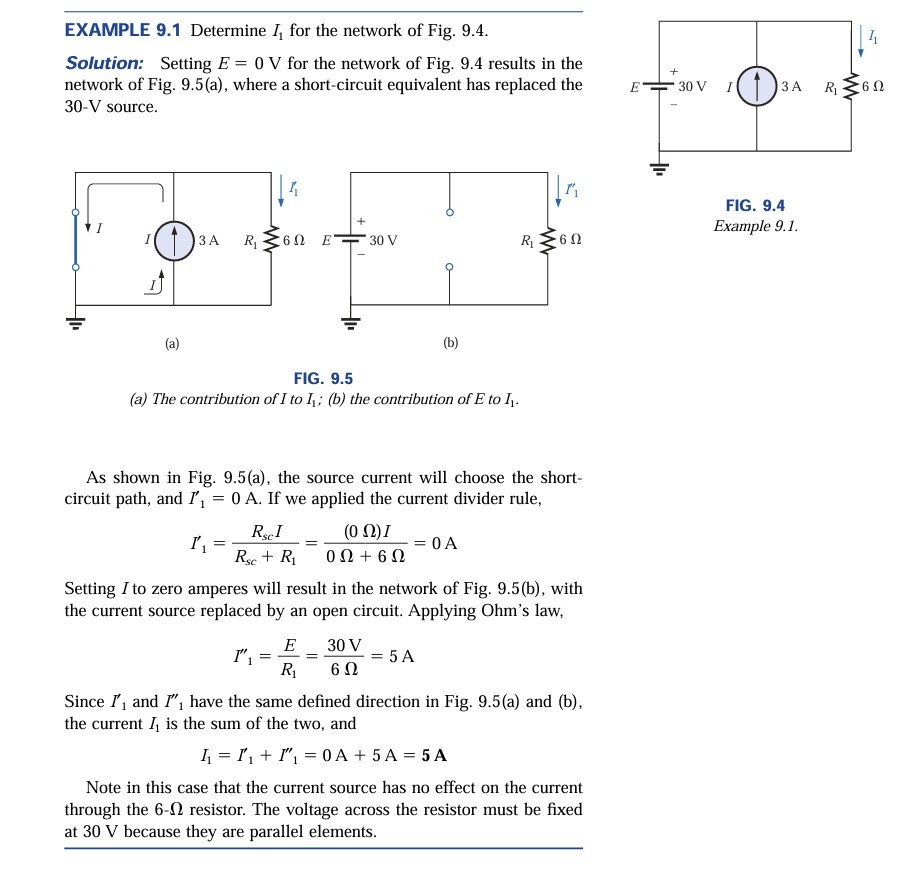
EXAMPLE 9.1 Determine \( I_{1} \) for the network of Fig. 9.4.
Solution: Setting \( E=0 \mathrm{~V} \) for the network of Fig. 9.4 results in the network of Fig. 9.5(a), where a short-circuit equivalent has replaced the \( 30-\mathrm{V} \) source.
(a)
(b)
FIG. 9.4
Example 9.1.
FIG. 9.5
(a) The contribution of \( I \) to \( I_{1} \); (b) the contribution of E to \( I_{1} \).
As shown in Fig. 9.5(a), the source current will choose the shortcircuit path, and \( I_{1}^{\prime}=0 \mathrm{~A} \). If we applied the current divider rule,
\[
I_{1}^{\prime}=\frac{R_{s c} I}{R_{s c}+R_{1}}=\frac{(0 \Omega) I}{0 \Omega+6 \Omega}=0 \mathrm{~A}
\]
Setting \( I \) to zero amperes will result in the network of Fig. 9.5(b), with the current source replaced by an open circuit. Applying Ohm's law,
\[
I_{1}^{\prime \prime}=\frac{E}{R_{1}}=\frac{30 \mathrm{~V}}{6 \Omega}=5 \mathrm{~A}
\]
Since \( I_{1}^{\prime} \) and \( I^{\prime \prime}{ }_{1} \) have the same defined direction in Fig. 9.5(a) and (b), the current \( I_{1} \) is the sum of the two, and
\[
I_{1}=I_{1}^{\prime}+I_{1}^{\prime \prime}=0 \mathrm{~A}+5 \mathrm{~A}=\mathbf{5} \mathbf{A}
\]
Note in this case that the current source has no effect on the current through the \( 6-\Omega \) resistor. The voltage across the resistor must be fixed at 30 V because they are parallel elements.