1. Emitter Follower
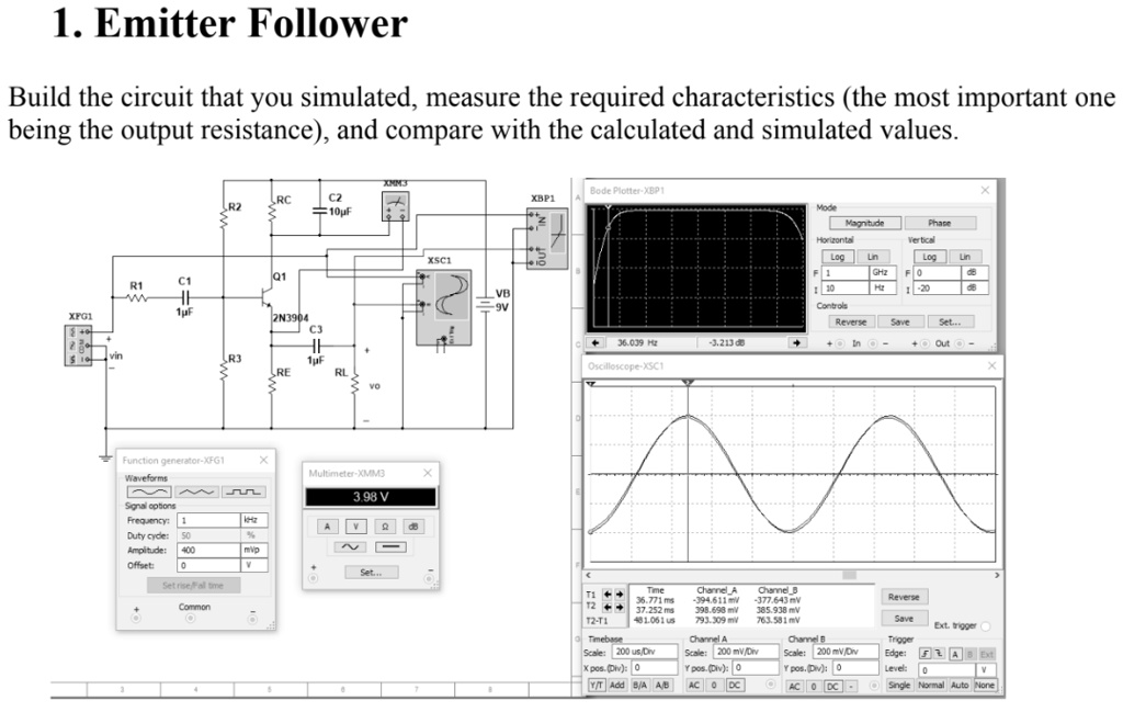
Build the circuit that you simulated, measure the required characteristics (the most important one
being the output resistance), and compare with the calculated and simulated values.
RC
R2
C2
10µF
C1
Q1
R1
XFG1
1µF
2N3904
C3
vin
R3
1µF
RE
RL
vo
XSC1
Function generator-XFG1
X
Waveforms
Multimeter-XMM3
X
~
3.98 V
Signal options
Frequency:
1
AV
Duty cyde: 50
Amplitude: 400
Offset:
Set rise/Fall time
mVp
~
VB
-9V
Bode Plotter-XBP1
XBP1
36.039 Hz
Oscilloscope-XSC1
-3.213 d
X
Mode
Magnitude
Phase
Horizontal
Log
1
GH
Vertical
Log
0
10
Controls
Reverse
Save
Set
In
Out
T2
Time
36.771 ms
37.252 ms
481.061 us
Channel A
-394.611 mV
398.698 mV
793.309 mV
Channel A
12-T1
Timebase
Scale: 200 us/Div
Xpos. (Div): 0
Y pos. (Div): 0
Channel B
-377.643 mV
385.938 mV
Scale: 200 mV/Div
Y/T Add B/A A/B AC DC
763.581 mV
Channel B
Scale: 200 mV/Div
Y pos. (Div): 0
AC DC-
Reverse
Save
Trigger
Ext. trigger
Edge: FAB Ext
Level: 0
Single Normal Auto None