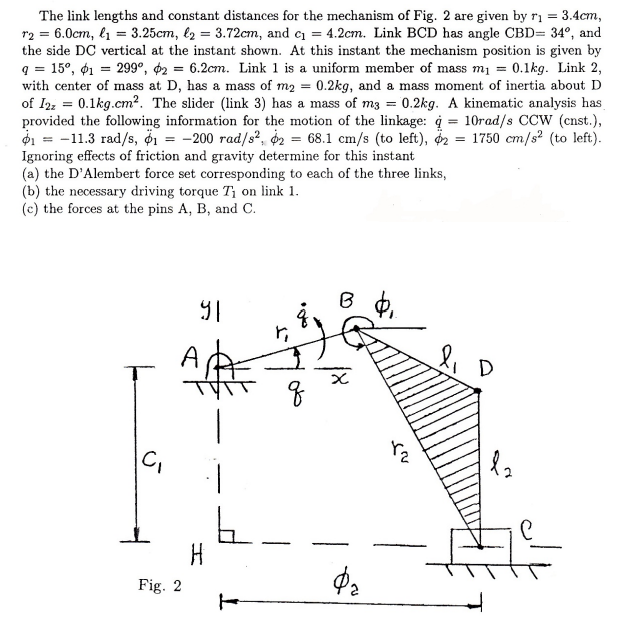
The link lengths and constant distances for the mechanism of Fig. 2 are given by \( r_{1}=3.4 \mathrm{~cm} \), \( r_{2}=6.0 \mathrm{~cm}, \ell_{1}=3.25 \mathrm{~cm}, \ell_{2}=3.72 \mathrm{~cm} \), and \( c_{1}=4.2 \mathrm{~cm} \). Link BCD has angle \( \mathrm{CBD}=34^{\circ} \), and the side DC vertical at the instant shown. At this instant the mechanism position is given by \( q=15^{\circ}, \phi_{1}=299^{\circ}, \phi_{2}=6.2 \mathrm{~cm} \). Link 1 is a uniform member of mass \( m_{1}=0.1 \mathrm{~kg} \). Link 2, with center of mass at D , has a mass of \( m_{2}=0.2 \mathrm{~kg} \), and a mass moment of inertia about D of \( I_{2 z}=0.1 \mathrm{~kg} . \mathrm{cm}^{2} \). The slider (link 3) has a mass of \( m_{3}=0.2 \mathrm{~kg} \). A kinematic analysis has provided the following information for the motion of the linkage: \( \dot{q}=10 \mathrm{rad} / \mathrm{s} \) CCW (cnst.), \( \dot{\phi}_{1}=-11.3 \mathrm{rad} / \mathrm{s}, \ddot{\phi}_{1}=-200 \mathrm{rad} / \mathrm{s}^{2}, \dot{\phi}_{2}=68.1 \mathrm{~cm} / \mathrm{s} \) (to left), \( \ddot{\phi}_{2}=1750 \mathrm{~cm} / \mathrm{s}^{2} \) (to left). Ignoring effects of friction and gravity determine for this instant
(a) the D'Alembert force set corresponding to each of the three links,
(b) the necessary driving torque \( T_{1} \) on link 1.
(c) the forces at the pins A, B, and C.