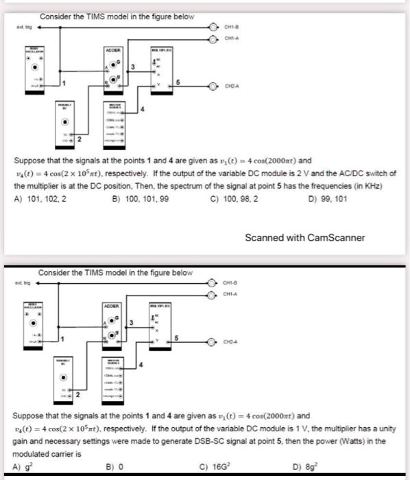
Consider the TIMS model in the figure below
CH1-B
CH1-A
2
ADDER
3
5
CHOA
Suppose that the signals at the points 1 and 4 are given as $v_1(t) = 4 \cos(2000\pi t)$ and
$v_2(t) = 4 \cos(2 \times 10^5 \pi t)$, respectively. If the output of the variable DC module is 2 V and the AC/DC switch of
the multiplier is at the DC position, Then, the spectrum of the signal at point 5 has the frequencies (in KHz)
A) 101, 102, 2
B) 100, 101, 99
C) 100, 98, 2
D) 99, 101
Consider the TIMS model in the figure below
ext big
CHI-B
CHI-A
2
ADDIER
3
5
CHOA
Scanned with CamScanner
Suppose that the signals at the points 1 and 4 are given as $v_1(t) = 4 \cos(2000\pi t)$ and
$v_2(t) = 4 \cos(2 \times 10^5 \pi t)$, respectively. If the output of the variable DC module is 1 V, the multiplier has a unity
gain and necessary settings were made to generate DSB-SC signal at point 5, then the power (Watts) in the
modulated carrier is
A) $g^2$
B) 0
C) $16G^2$
D) $8g^2$