VCC
VOC
R1
C1
Vout
R2
C2
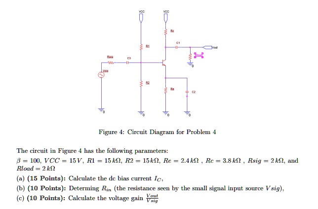
Figure 4: Circuit Diagram for Problem 4
The circuit in Figure 4 has the following parameters:
$\beta$ = 100, VCC = 15V, R1 = 15 $k\Omega$, R2 = 15$k\Omega$, Re = 2.4$k\Omega$, Rc = 3.8 $k\Omega$, Rsig = 2 $k\Omega$, and
Rload = 2 $k\Omega$
(a) (15 Points): Calculate the dc bias current $I_C$,
(b) (10 Points): Determining $R_{in}$ (the resistance seen by the small signal input source $V_{sig}$),
(c) (10 Points): Calculate the voltage gain $\frac{V_{out}}{V_{sig}}$