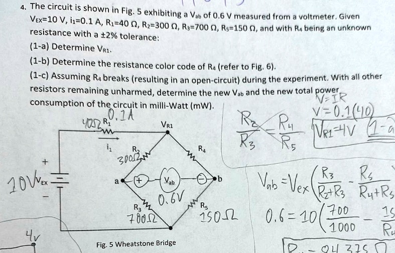
4. The circuit is shown in Fig. 5 exhibiting a $V_{ab}$ of 0.6 V measured from a voltmeter. Given
$V_{ex}$=10 V, $i_1$=0.1 A, $R_1$=40 Ω, $R_2$=300 Ω, $R_3$=700 Ω, $R_5$=150 Ω, and with $R_4$ being an unknown
resistance with a ±2% tolerance:
(1-a) Determine $V_{R1}$.
(1-b) Determine the resistance color code of $R_4$ (refer to Fig. 6).
(1-c) Assuming $R_4$ breaks (resulting in an open-circuit) during the experiment. With all other
resistors remaining unharmed, determine the new $V_{ab}$ and the new total power
consumption of the circuit in milli-Watt (mW).
$\frac{R_2}{R_3} = \frac{R_4}{R_5}$
$V_{ab} = V_{ex} (\frac{R_3}{R_2+R_3} - \frac{R_5}{R_4+R_5})$
$V = IR$
$V = 0.1(40)$
$V_{R1} = 4V$