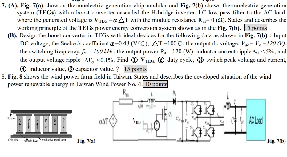
7. (A). Fig. 7(a) shows a thermoelectric generation chip modular and Fig. 7(b) shows thermoelectric generation system (TEGs) with a boost converter cascaded the H-bridge inverter, LC low pass filter to the AC load, where the generated voltage is $V_{TEG} = \alpha \Delta T$ with the module resistance $R_m = 0 (\Omega)$. States and describes the working principle of the TEGs power energy conversion system shown as in the Fig. 7(b). 5 points
(B). Design the boost converter in TEGs with ideal devices for the following data as shown in Fig. 7(b): Input DC voltage, the Seebeck coefficient $\alpha = 0.48 (V/°C)$, $\Delta T = 100°C$, the output dc voltage, $V_{dc} = V_o = 120 (V)$, the switching frequency, $f_s = 100 kHz$, the output power $P_o = 120 (W)$, inductor current ripple $\Delta i_L \leq 5\%$, and the output voltage ripple $\Delta V_o \leq 0.1\%$. Find ① $V_{TEG}$, ② duty cycle, ③ switch peak voltage and current, ④ inductor value, ⑤ capacitor value.? 15 points
8. Fig. 8 shows the wind power farm field in Taiwan. States and describes the developed situation of the wind power renewable energy in Taiwan Wind Power No. 4. 10 points