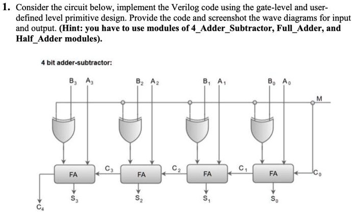
1. Consider the circuit below, implement the Verilog code using the gate-level and user-
defined level primitive design. Provide the code and screenshot the wave diagrams for input
and output. (Hint: you have to use modules of 4_Adder_Subtractor, Full_Adder, and
Half_Adder modules).
4 bit adder-subtractor:
B3 A3
B2 A2
B1 A1
Bo Ao
M
C3
C2
C1
FA
FA
FA
FA
Co
S2
S1
So
S3
C4