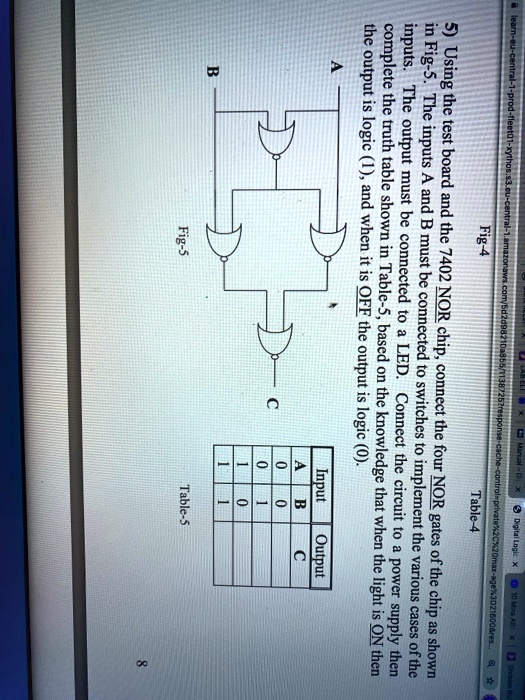
5) Using the test board and the 7402 NOR chip, connect the four NOR gates of the chip as shown in Fig-5. The inputs A and B must be connected to switches to implement the various cases of the inputs. The output must be connected to a LED. Connect the circuit to a power supply then complete the truth table shown in Table-5, based on the knowledge that when the light is ON then the output is logic (1), and when it is OFF the output is logic (0).