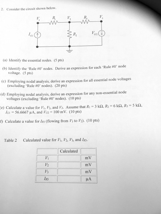
2. Consider the circuit shown below.
$I_{G1}$
$R_1$
$V_1$
$R_2$
$V_2$
$R_3$
$V_3$
$R_2$
$V_{G2}$+
(a) Identify the essential nodes. (5 pts)
(b) Identify the 'Rule #0' nodes. Derive an expression for each 'Rule #0' node
voltage. (5 pts)
(c) Employing nodal analysis, derive an expression for all essential node voltages
(excluding 'Rule #0' nodes). (20 pts)
(d) Employing nodal analysis, derive an expression for any non-essential node
voltages (excluding 'Rule #0' nodes). (10 pts)
(e) Calculate a value for $V_1$, $V_2$, and $V_3$. Assume that $R_1 = 3 k\Omega$, $R_2 = 6 k\Omega$, $R_3 = 5 k\Omega$,
$I_{G1} = 56.6667 \mu A$, and $V_{G2} = 100 mV$. (10 pts)
(f) Calculate a value for $I_{R3}$ (flowing from $V_3$ to $V_2$). (10 pts)
Table 2 Calculated value for $V_1$, $V_2$, $V_3$, and $I_{R3}$.
Calculated
$V_1$
mV
$V_2$
mV
$V_3$
mV
$I_{R3}$$\mu A