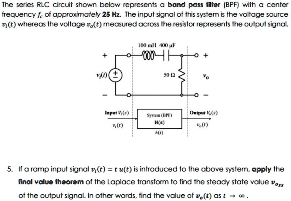
The series RLC circuit shown below represents a band pass filter (BPF) with a center
frequency $f_c$ of approximately 25 Hz. The input signal of this system is the voltage source
$v_i(t)$ whereas the voltage $v_o(t)$ measured across the resistor represents the output signal.
100 mH 400 µF
+ +
$v_i(t)$ 50 ? $v_o$
- -
Input $V_i(s)$
$v_i(t)$
System (BPF)
$H(s)$
Output $V_o(s)$
$v_o(t)$
h(t)
5. If a ramp input signal $v_i(t) = t u(t)$ is introduced to the above system, apply the
final value theorem of the Laplace transform to find the steady state value $v_{oss}$
of the output signal. In other words, find the value of $v_o(t)$ as $t \to \infty$.