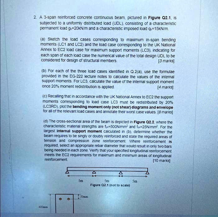
2A 3-span reinforced concrete continuous beam, pictured in Figure Q2.1, is subjected to a uniformly distributed load (UDL) consisting of a characteristic permanent load g = 20 kN/m and a characteristic imposed load q = 15 kN/m.
Sketch the load cases corresponding to maximum in-span bending moments LC1 and LC2, and the load case corresponding to the UK National Annex to EC2 load case for maximum support moments (LC3), indicating for each span of each load case the numerical value of the total design UDL to be considered for design of structural members [3 marks].
b) For each of the three load cases identified in Q.2a, use the formulas provided in the EG-222 lecture notes to calculate the values of the internal support moments. For LC3, calculate the value of the internal support moment once 20% moment redistribution is applied [4 marks].
c) Recalling that in accordance with the UK National Annex to EC2, the support moments corresponding to load case LC3 must be redistributed by 20% (LC3RD), plot the bending moment (only, not shear) diagrams and envelope for all of the relevant load cases and annotate their worst-case values [8 marks].
d) The cross-sectional area of the beam is depicted in Figure Q2.2, where the characteristic material strengths are f = 500 N/mm² and f = 25 N/mm². For the largest internal support moment calculated in (b), determine whether the beam requires to be singly or doubly reinforced and state the required areas of tension and compression zone reinforcement, where reinforcement is needed in each zone. Verify that your specified longitudinal reinforcement meets the EC2 requirements for maximum and minimum areas of longitudinal reinforcement [10 marks].
5m
Sm
Sm Figure Q2.1 (not to scale)