Texts:
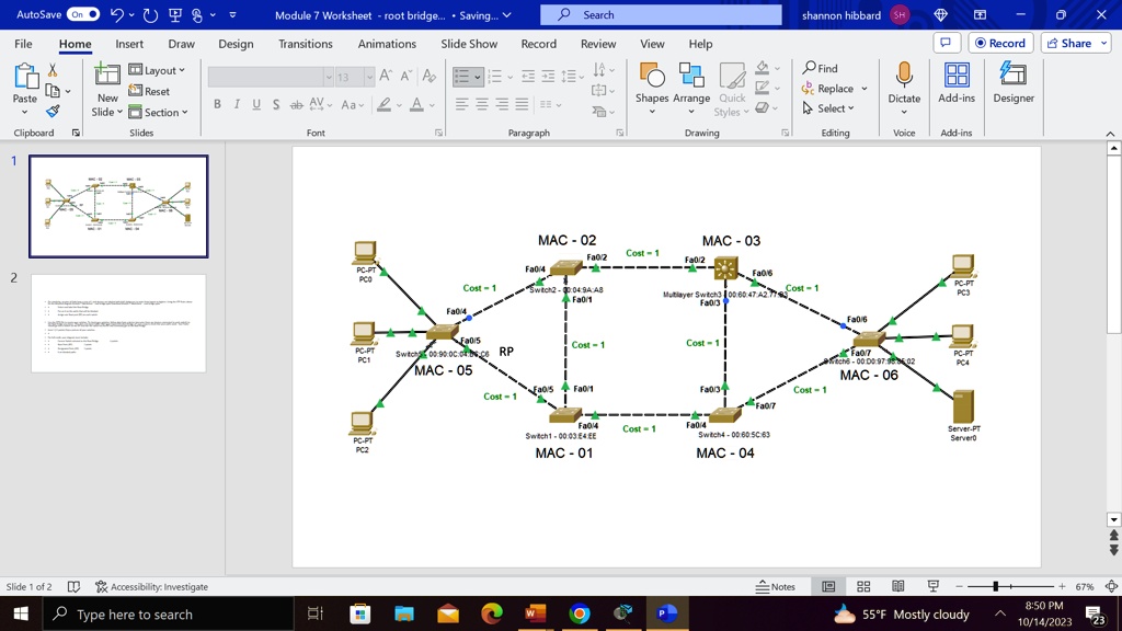
• For simplicity, assume all links have a cost of 1 and devices are labeled with MAC Addresses in order from lowest to highest. Using the STP Rules above for the attached diagram Module 7 Worksheet – root bridge.pptx Download Module 7 Worksheet – root bridge.pptx:
• Select and label the Root Bridge
• Put an X on the paths that will be blocked.
• Assign one Root port (RP) on each switch.
• Use the PPTX file to create your solution. To check your solution, follow data from a device (presume there are devices connected to each switch) to the Root Bridge you chose. This does not mean traffic ONLY goes toward the Root Bridge, it’s just a way to check that your paths work. Your frame should go into a switch via the DP and exit the switch via the RP and eventually get to the Root Bridge.
• Item 2 (11 points) Snip a picture of your solution.
• For full credit, your diagram must include:
- Correct Switch selected as the Root Bridge (4 points).
- Root Ports (RP) (2 points).
- Designated Ports (DP) (2 points).
- X on blocked paths
AutoSave On
V
v
Module 7 Worksheet - root bridge... Saving... V
Search
shannon hibbard SH
X
File
Home
Insert
Draw
Design Transitions
Animations
Slide Show Record Review
View
Help
O Record Share 88 Dictate Add-ins Designer
Layout v Reset New Slide v Section Slides
13 AAP B IU S abAY Aa DA
O Find chc Replace Select v Editing
=
[]v Shapes Arrange Quick Styles Drawing
Paste
I I
Clipboard
Font
Paragraph
Voice
Add-ins
^ A
MAC - 02 Fa0/2 Cost = 1 Fa0/4
MAC - 03
pc9
Fa0/6
Cost = 1
switch2 - @D:04:9AA8 A Fa0/1
Multilayer Switch300:60:47:A2.77
Cost =
C-PT PC3
Fa0/4
Fa0/5 Switch90.00.bes RP MAC-05
PC-PT PC1
Cost = 1
Cost = 1 1
CFa0/7 ch600.00:97:02 MAC-06 Cost = 1
Pp-PT PC4
Cost = 1
Fa0/5 4 Fa0/1
Fa0/3J
Fa0/4 Switch1 - 00:03:E4:EE MAC-01
Cost = 1
Fa0/4 Switch4 - 00:60:5C:63
PC-PT PC2
Server-PT Server0
MAC-04
Slide 1 of 2
Accessibility: Investigate
Notes
88
BE
67% 8:50 PM 10/14/2023 23
Type here to search
W
P
55F Mostly cloudy