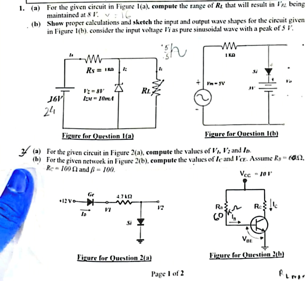
1. (a) For the given circuit in Figure 1(a), compute the range of $R_t$ that will result in $I_R$ being
maintained at 8 mA.
(b) Show proper calculations and sketch the input and output wave shapes for the circuit given
in Figure 1(b). consider the input voltage $V_i$ as pure sinusoidal wave with a peak of 5 V.
M
1 kΩ
$R_S$ = 1 kΩ た
Si
$V_{im}$=5V
16V
$V_i$=5V
$I_M$= 10mA
Δ
$R_L$
24
Figure for Question 1(a)
Figure for Question 1(b)
3 (a) For the given circuit in Figure 2(a), compute the values of $V_1$, $V_2$ and $I_D$.
(b) For the given network in Figure 2(b), compute the values of $I_C$ and $V_{CE}$. Assume $R_S$ = 600Ω,
$R_C$ = 100 Ω and β = 100.
$V_{CC}$=10 V
Ge
4.7 kΩ
12V
$I_B$
$V_1$
$V_2$
R
Si
$V_{OE}$
Figure for Question 2(a)
Page 1 of 2
$R_E$
Figure for Question 2(b)