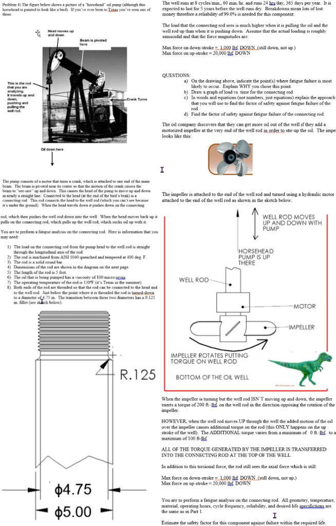
Problem 4) The figure below shows a picture of a "horsehead" oil pump (although this
horsehead is painted to look like a bird). If you've ever been to Texas you've seen one of
these.
Head moves up
and down
Beam is pivoted
here
The well runs at 8 cycles/min., 60 min./hr. and runs 24 hrs/day, 365 days per year. It is
expected to last for 5 years before the well runs dry. Breakdowns mean lots of lost
money therefore a reliability of 99.0% is needed for this component.
The load that the connecting rod sees is much higher when it is pulling the oil and the
well rod up than when it is pushing down. Assume that the actual loading is roughly
sinusoidal and that the force magnitudes are:
Max force on down-stroke = 1,000 lbf DOWN (still down, not up.)
Max force on up-stroke = 20,000 lbf DOWN
Oil down here
QUESTIONS:
a) On the drawing above, indicate the point(s) where fatigue failure is most
likely to occur. Explain WHY you chose this point.
b) Draw a graph of load vs. time for the connecting rod
c) In words and equations (not numbers, just equations) explain the approach
that you will use to find the factor of safety against fatigue failure of the
rod.
d) Find the factor of safety against fatigue failure of the connecting rod.
The oil company discovers that they can get more oil out of the well if they add a
motorized impeller at the very end of the well rod in order to stir-up the oil. The impe
looks like this:
I
The pump consists of a motor that turns a crank, which is attached to one end of the main
beam. The beam is pivoted near its center so that the motion of the crank causes the
beam to "see-saw" up and down. This causes the head of the pump to move up and down
in nearly a straight line. Connected to the head (at the end of the bird's beak) is a
connecting rod. This rod connects the head to the well rod (which you can't see because
it's under the ground). When the head travels down it pushes down on the connecting
rod, which then pushes the well rod down into the well. When the head moves back up it
pulls on the connecting rod, which pulls up the well rod, which sucks oil up with it.
You are to perform a fatigue analysis on the connecting rod. Here is information that you
may need:
1) The load on the connecting rod from the pump head to the well rod is straight
through the longitudinal axis of the rod.
2) The rod is machined from AISI 1040 quenched and tempered at 400 deg. F.
3) The rod is a solid round bar.
4) Dimensions of the rod are shown in the diagram on the next page.
The impeller is attached to the end of the well rod and turned using a hydraulic motor
attached to the end of the well rod as shown in the sketch below:
WELL ROD MOVES
UP AND DOWN WITH
PUMP
HORSEHEAD
PUMP IS UP
THERE
5) The length of the rod is 5 feet.
6) The oil that is being pumped has a viscosity of 100 micro-poise.
7) The operating temperature of the rod is 150°F (it's Texas in the summer).
8) Both ends of the rod are threaded so that the rod can be connected to the head and
WELL ROD
to the well rod. Just below the point where it is threaded the rod is turned-down
to a diameter of 4.75 in. The transition between these two diameters has a 0.125
in. fillet (see sketch below).
IMPELLER ROTATES PUTTING
TORQUE ON WELL ROD
R.125
BOTTOM OF THE OIL WELL
MOTOR
-IMPELLER
$4.75
$5.00
When the impeller is turning but the well rod ISN'T moving up and down, the impeller
exerts a torque of 200 ft-lbf. on the well rod in the direction opposing the rotation of the
impeller.
HOWEVER, when the well rod moves UP through the well the added motion of the oil
over the impeller causes additional torque on the rod (this ONLY happens on the up
stroke of the well). The ADDITIONAL torque varies from a minimum of 0 ft-lbf. to a
maximum of 100 ft-lbf.
ALL OF THE TORQUE GENERATED BY THE IMPELLER IS TRANSFERRED
INTO THE CONNECTING ROD AT THE TOP OF THE WELL.
In addition to this torsional force, the rod still sees the axial force which is still:
Max force on down-stroke = 1,000 lbf DOWN (still down, not up.)
Max force on up-stroke = 20,000 lbf DOWN
You are to perform a fatigue analysis on the connecting rod. All geometry, temperature,
material, operating hours, cycle frequency, reliability, and desired life specifictions are
the same as in Part 1.
I
Estimate the safety factor for this component against failure within the required life.