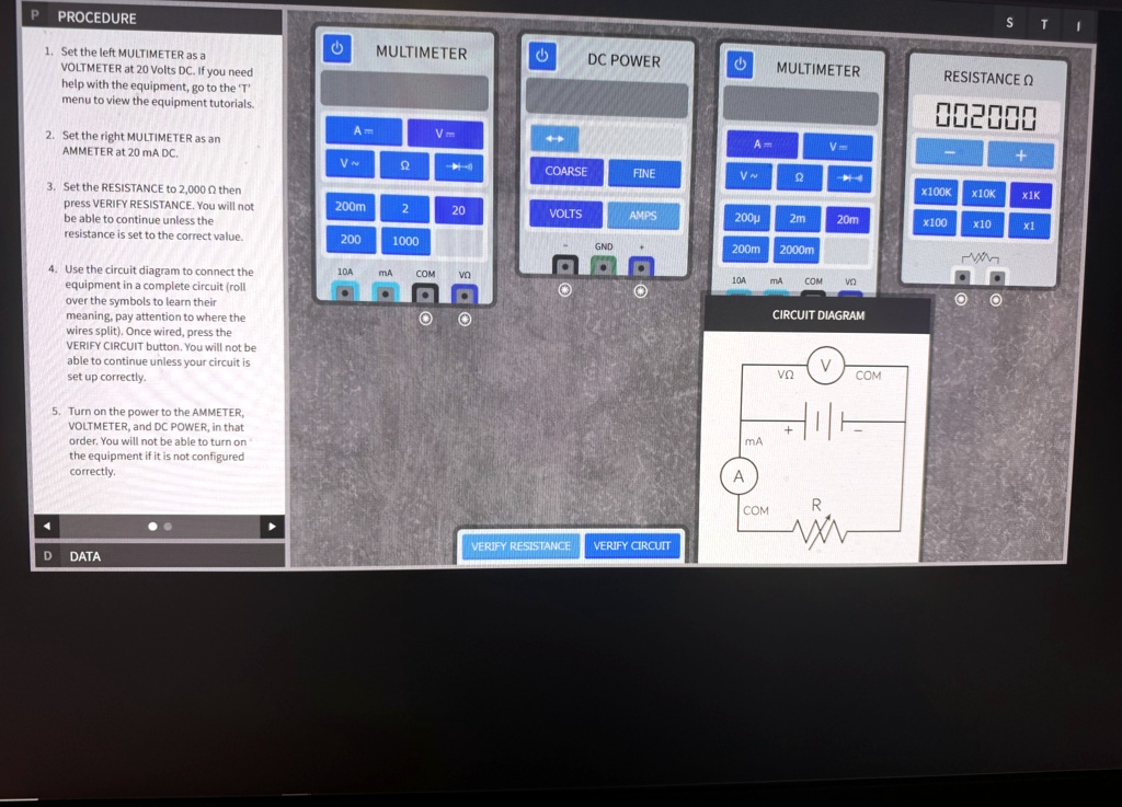
1. Set the left MULTIMETER as a VOLTMETER at 20 Volts DC. If you need help with the equipment, go to the 'T' menu to view the equipment tutorials.
2. Set the right MULTIMETER as an AMMETER at 20 mA DC.
3. Set the RESISTANCE to 2,000 0 then press VERIFY RESISTANCE. You will not be able to continue unless the resistance is set to the correct value.
4. Use the circuit diagram to connect the equipment in a complete circuit (roll over the symbols to learn their meaning, pay attention to where the wires split). Once wired, press the VERIFY CIRCUIT button. You will not be able to continue unless your circuit is set up correctly.
5. Turn on the power to the AMMETER, VOLTMETER, and DC POWER, in that order. You will not be able to turn on the equipment if it is not configured correctly.
D DATA
MULTIMETER
A
V
V
Ω
COARSE
FINE
VOLTS
AMPS
GND
MULTIMETER
A
V
V
Ω
200μ 2m
20m
200m 2000m
10A
MA COM
RESISTANCE Ω
002000
+
X100K X10K X1K
x100 x10
x1
CIRCUIT DIAGRAM
V
νΩ
COM
MA
A
COM
R
VERIFY RESISTANCE VERIFY CIRCUIT