A. Scott
MUX 3
RALU MUX 1
A
M3:0
0
LOAD_RO
R_ALU/R1
D
CE
LOAD_R1
Reg R0
C
CLR
RST
CE
Reg R1
CLR
RST(asyn)
LOAD_OP
MUX 2
0
4
MUX 2
0
4
CE
A_OR1
D Reg OP(1:0)
output
port
CLK
C
CLR
RST
M2
D
CLK
MI
ALU
ALU_OUT
LOAD(ALU)
LOADI (ALU)
ADD(1010)
ADD(1010)
SUB
MUX 4
MUX 5
0
R_JR
IR(7:5)
MS
IR(3:0)
A4
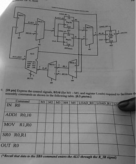
4. [20 pts] Express the control signals, 0/1/d (for M1-M5, and register Loads) required to facilitate the
assembly commands as shown in the following table. [0.5 pts/ea.]
M1 M2 M3 M4 M5 LOAD_R0 LOAD_R1 LO
Command
IN R0
ADDI R0,10
MOV R1,R0
SRO R0,R1
OUT R0
(*Recall that data to the SRO command enters the ALU through the R_IR signal)